
Why 3D Printing Is Changing Watch Movements
What makes a mechanical watch tick is a tiny choreography of gears, springs, pallets, and escapement, all timed with micron-scale precision. Precision matters because small variances become minutes per day. 3D printing changes the rules by allowing new geometries, part consolidation, and rapid iteration that traditional machining or stamping cannot match.
Additive manufacturing opens paths to lighter, integrated, and customized movement components. It lets designers embed functions, print complex tooth profiles, and test novel materials quickly. This introduction frames a technical but accessible tour of the key technologies, CAD strategies, printing steps, and trade-offs that determine whether a 3D-printed movement can truly keep time.

3D-Printable Watch Movement You Can Use Now
Mechanical Movement Fundamentals: The Anatomy of a Tick
Core functional blocks
A mechanical movement is a simple-but-precise energy flow system built from five functional blocks:
Think of the escapement as a gatekeeper: the mainspring pushes, the train multiplies and times that push, and the escapement “meters” tiny energy packets to the balance so each swing gets just enough energy to keep going.
How energy flows and is metered
When you wind, the barrel stores potential energy. That energy travels down the train, arriving at the escape wheel which tries to spin free but is intermittently stopped by the pallet fork. Each time the pallet gives, the escape wheel transfers a precise impulse to the balance. The balance’s oscillation period, determined by its inertia and the hairspring’s stiffness, defines the watch’s tick rate.
Practical tip: when checking a movement, look at amplitude (typical healthy amplitude 250–320° for many wristwatches) and beat error; they reveal whether the balance is receiving consistent impulses.
Critical tolerances and finishes (practical targets)
Actionable advice: measure pivot runout, verify crown wheel backlash, and polish escape teeth/contact faces. Even small roughness or a few microns of misalignment change timekeeping from COSC-level accuracy (≈-4/+6 s/day) to minutes per day.
Additive Technologies and Materials Suitable for Watch Components
Which 3D processes actually work for watches
Not all 3D printing is equal for watchmaking. Useful options fall into two camps:
Material-role matching (practical guide)
Pick materials by mechanical need:
Match properties—hardness for tooth wear, modulus for dimensional stability, fatigue strength for thin spokes, and thermal stability for rate stability.
Trade-offs and immediate practices
AM introduces surface roughness, anisotropy, and potential porosity that shorten wear life if untreated. Best practices: orient critical surfaces to minimize layer steps, remove subsurface porosity with HIP, follow with CNC finish‑turning for pivots and mirror polish for escapement faces, and consider PVD coatings for wear. Two-photon or fine‑grain SLM plus post‑machining is a common hybrid route.
Next, we’ll look at how those choices drive printing parameters and the essential post‑processing steps that turn a printed blank into a working movement component.
Design for Additive: CAD Strategies, Precision, and Functional Integration
Model with function-first datums
Start by defining functional datums in CAD: the pivot plane, escape wheel axis, and dial plane become primary reference surfaces. Model witness flats, assembly bosses, and kinematic datum spheres so every part can be measured and fixtured the same way. These references let inspectors and CNC finishing jigs restore true geometry after printing.
Compensate for shrinkage and distortion
Additive builds distort. Measure your machine/process: print calibration coupons across the plate, quantify X/Y/Z scale drift, then apply anisotropic compensation (e.g., X+0.08%, Y−0.02%, Z by layer shrink) as a CAD scale feature or slicer offset. For SLM, include stiffness ribs or sacrificial stiffeners that are removed after heat treatment to reduce warpage.
Orientation, supports, and surface strategy
Orient so critical faces are either parallel to the highest-resolution axis or on surfaces that will be machined. Place supports off functional geometries—on non-load bearing flanks or removable tabs—and design micro‑fillet reliefs where supports meet finished edges to simplify cleanup. For pivot holes and jewel seats, expect to design finishing allowances rather than final-size features.
Topology optimization and lattices
Use topology optimization to remove unnecessary mass while maintaining load paths: optimize plates for bending stiffness around pivot islands. Replace solid pockets with graded lattices (gyroid or beam lattices) to cut mass and tune stiffness; lattice parameters can be exported as STL bodies and blended to smooth stress concentrations.
Monolithic integration and practical tips
Exploit AM by integrating gear carriers, cam profiles, or press‑fit jewel bores into a single plate—then machine only the critical contact faces. Practical rules: leave 0.05–0.2 mm finishing stock on pivots and bores (process dependent), locate assembly holes with hardened steel dowel bosses in CAD, and add inspection pads for CMM probing.
These CAD-first practices set the stage for process tuning—next we’ll examine the printing parameters and post-processing steps that turn those designs into functioning components.
From Powder/Resin to Functional Part: Printing Parameters and Post-Processing
Print settings that determine detail and strength
Small changes at the machine level change whether a component is a precision carrier or scrap. Key knobs:
Support removal, cleaning, and early inspection
After demolding or de-powdering:
Heat treatment, HIP and surface finishing
Critical steps to turn a printed blank into a bearing-ready part:
Why certain features are finished or fitted post-print
Printed surfaces rarely achieve the sub-micron roundness, hardness, and spring temper required for pivots, hairsprings, or jewels. Hairsprings need metallurgy and tempering impractical in AM; jewels (synthetic ruby) and ultra-smooth pivots are better manufactured and then pressed or pinned into 3D‑printed plates. The common workflow: print, HIP/anneal, machine the functional bores, then fit high-precision inserts—this hybrid approach yields the best of both worlds and scales to production.
Assembly, Regulation, and How a 3D-Printed Movement Actually Runs
Fitting jewels, bearings and bridges
Printed plates and bridges are prepared like any movement blank but with tighter QC: machine the printed jewel seats to size, then press-fit or heat-set synthetic rubies (usually 0.1–0.3 mm interference). Key tips:
Installing the gear train and escapement
Assembly follows classical order: mainspring barrel → center/third/fourth wheels → escapement. Practical points for AM parts:
Lubrication and surface treatment
Printed metals can soak or wick lubricants differently. Best practices:
Regulation: measuring amplitude, rate, beat error
Use a timing machine (e.g., Witschi) and measure:
Iteration and real-world testing
Designers iterate: run 72–240 hour stability tests, log positional deviations, then tweak tooth profiles, clearances, and surface finishes. The printed movement will often require a few mechanical and lubrication cycles to “bed in” — think of it as engineering by running, tuning both geometry and tribology before final timing targets are met.
Limitations, Reliability Concerns, and Future Opportunities
Current technical limits and failure modes
Additive manufacturing brings new failure modes to horology. Printed metals can suffer fatigue and accelerated wear from microstructural heterogeneity; layer-induced anisotropy and residual porosity create stress concentrators; and rough as-built surfaces increase friction at pivots, pallets and gear teeth. Producing ultra-elastic, high-stability parts such as Nivarox hairsprings remains largely out of scope for current AM routes — conventional metallurgy still wins for hairsprings and critical balance components.
Mitigation strategies and actionable QA
Practical steps watchmakers use today:
These are practical, immediately actionable steps—machine critical interfaces, insist on HIPed powders where possible, and run micro-CT on first-off batches.
Forward-looking opportunities
AM still opens doors no subtractive methods can:
Where AM is most useful today
Best uses today: rapid prototyping, bespoke limited editions and experimental complications where geometry or integration matters more than decades-long service histories. For AM to go mainstream, hairspring production, long-term wear data, and economically viable QA chains must improve.
Next: Putting It Together — when and why 3D‑printed movements make practical sense.
Putting It Together: When and Why 3D-Printed Movements Make Sense
3D printing expands movement architecture by enabling complex geometries, part consolidation, and rapid iteration that are impractical with traditional machining—ideal for prototypes, bespoke complications, and design-forward limited runs. The trade-offs are clear: printers and materials can achieve remarkable precision but demand post-processing, surface finishing, and calibration to approach the reliability of established metal movements.
For watchmakers and designers, additive is a tool for innovation rather than wholesale replacement: use it to explore new kinematics, reduce part count, or accelerate development while retaining critical components in proven materials where longevity matters. Enthusiasts should weigh novelty and customization against long-term serviceability. Experiment and collaborate with materials specialists to unlock additive’s practical benefits.
This line made me laugh: ‘the anatomy of a tick’ — ingenious. 😄
But seriously, the mechanical fundamentals section was great for newbies. I still don’t get why pinion hardness is so critical though?
Pinion hardness matters because pinion teeth suffer concentrated contact stress; soft teeth quickly deform, changing backlash and timing. That’s why metal pinions are often preferred.
Yep — even tiny wear changes amplitude. Printed plastics may swell or wear differently; surface treatments can help but only to a point.
Also, hardened pinions help maintain long-term meshing accuracy. If you want longevity, focus on metal on critical wear points.
Great deep dive — loved the CAD strategy section.
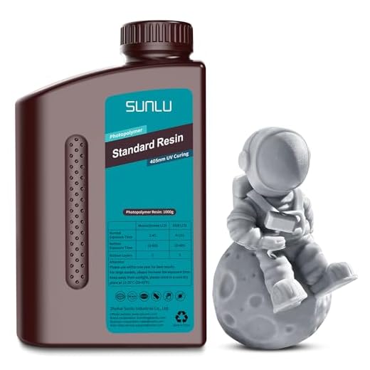
I’m a hobbyist and the part about integrating pivots into the print finally clicked for me. I do have one practical q: are standard resins like SUNLU good enough for prototype gears, or should I be using special engineering resins to avoid rapid wear?
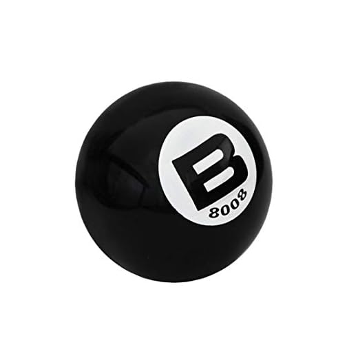
Also, the bit about using a Bergeon 8008 ball for opening cases was funny — feels like a cheat code 😂
Thanks for including the tool list, saved me a few searches!
Also watch the post-curing time — undercured resin is WAY weaker. Had a gear snap because I rushed it once 😅
I’ve used SUNLU for hobby prints — decent for testing. If you plan to run a movement for hours, consider engineering resin or a hybrid: resin for bridges, brass for pinions.
For prototypes SUNLU works well for form and fit — it prints fine and is cheap. For functional gears you’ll want a tougher resin or even metal if possible; photopolymers can be brittle long-term. Glad the Bergeon shout-out helped!
I appreciated the practical shopping list. The 155-Piece Complete Watch Repair Tool Kit seems like a solid starter — anyone here used it specifically for assembling printed parts?
Used it for printed prototypes — the screwdrivers are decent but replace the flimsy spring bars if you need precision. Otherwise, solid value.
Yes, a basic kit like that covers screwdrivers, tweezers, and hand tools which are perfectly fine for printed prototypes. For very delicate printed parts you might want softer tweezers or 3D-printed jigs to avoid crushing.
This article convinced me to stop overthinking and just prototype something small.
Plan: print a test bridge + escape wheel with SUNLU for fit, then swap in a Seagull escapement to test regulation.
Wish me luck!
Love the plan — iterative testing is the way. Start with single-component trials, check mesh and end-shake before assembling everything.
Good luck! Take lots of photos — documenting tolerances helps you iterate faster.
I actually bought the Bergeon 8008 ball after reading this. Best $50 I ever spent for opening old cases. Worth mentioning: it doesn’t replace a proper case wrench for screw-backs, but for friction-fit it’s magic.
Glad it worked for you! Good tip about wrench vs ball — we’ll clarify that distinction in the gear roundup.
I use mine all the time. Also, keep it clean — oil and debris reduce grip.
Same here — saved me from using a butter knife. 😂 Pro tip: use a little tape to protect polished cases when using the ball.
Loved the limitations section. Not everything needs to be printed, and the piece made that clear.
Still, I wonder: are we close to seeing full 3D-printed movements in affordable watches, or is that still niche/artisanal?
If someone cracks a cheap, durable printed escapement, the game changes. Until then, metal reigns.
I think within a decade we’ll see small brands offering printed components in entry-level mechanicals. But full printed calibers? probably longer.
Good question. For now it’s niche—mostly prototypes and experimental pieces. Cost and long-term reliability need to improve before mainstream adoption, but hybrid approaches are gaining ground.
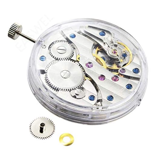
Pretty technical article but very informative. The assembly section made me want to buy that 155-Piece Complete Watch Repair Tool Kit and try a hand-wind movement like the EASWEL Seagull ST36 6497.
Question: how realistic is it to replace just the mainspring with aftermarket parts when experimenting with 3D-printed components?
Agreed. I paired a printed gear train with a Seagull mainspring once. Worked surprisingly well for short runs, but lubrication and alignment are critical.
It’s realistic and smart — use proven mainsprings and escapement parts initially. Mixing printed bridges/gears with reliable metal power sources reduces variables during testing.
For those asking about long-term wear: try plating printed gears or using PVD on metal inserts. Makes a big difference.
Not cheap, but if you want durability it’s worth exploring.
Plating can mask small print defects too. But watch for added thickness affecting tolerances.
Good suggestion — metallization or inserting hardened pivots helps. Adds complexity but boosts wear resistance significantly.
I’ve seen electroless nickel coats on prints look decent. Adhesion depends on surface prep though.
Not a watch person usually but this read felt like a sci-fi manual for tiny machines. Super fun.
One concern though: environmental impact of disposable resins. Any thoughts on recycling or less-toxic alternatives?
I started using less-toxic uricure resins and a closed-loop solvent system — expensive upfront but better long term.
Great point. Resin waste is an issue. Some labs filter and reuse wash solvents, and a few companies are developing bio-based resins. We’ll look into sustainable workflows in a future piece.
Also, solidify waste with UV before disposal per local regulations. Don’t pour uncured resin down the drain!
Had a laugh at the ‘functional integration’ section — designing a pivot and a lubrication channel into one print is wild.
But how do you clean resin residues from tiny hollow channels? Sounds like a nightmare.
Agreed — I add small inspection ports in CAD and use a syringe with isopropyl to flush channels, then air-dry and UV-cure.
Sometimes inserting a thin wire to clear supports helps before final curing. Tiny brushes too.
It can be tricky. Ultrasonic baths, pressured air, and solvent flushing are common. Also designing access holes and using soluble supports makes cleaning easier.
Skeptical take: printed movements feel like a gimmick for Instagram micro-brands to me unless they prove long-term reliability. The article covered that but I wanted more hard-life testing data.
Where are the 1,000-hour run tests?
Many creators only publish short-run videos. Transparency is an issue. Hoping for third-party endurance tests soon.
Fair point. Long-duration testing is limited publicly. We’re collating data from a few labs and indie makers working on 500–2,000 hour benches and will publish when available.
Agreed — without standardized tests it’s hard to compare. Until then, buyer beware.
Small nit: the CAD tips are solid but someone should make a library of printable watch component templates. That would accelerate learning.
Anyone know if such a repo exists?
Some Thingiverse packs help, but tolerances are hit-or-miss. A curated, tolerance-checked repo would be gold.
I have a small set of parametric gear models I can share — DM if you want them.
There are a few community repos and private collections. We’ll link an updated list in the follow-up and consider hosting a curated library ourselves.
Minor nitpick: the section on printing parameters didn’t mention environmental controls much. Temp and humidity in my garage printer area make a huge diff for resin prints.
Otherwise solid read 👍
You’re right — environmental control is crucial, especially for consistent layer adhesion and post-curing. We’ll add a follow-up with best practices for workshop conditions.
Totally. My prints warped until I stopped printing in the shed in winter. Space heater + silica desiccant helped a lot.
Really appreciated the ‘when and why’ section. Gives context beyond the tech hype.
One small request: Could you add a quick decision flowchart for makers — e.g., prototype? yes/no -> print metal? -> buy Seagull? That would be super helpful for beginners.
Yes please — a step-by-step would save me from chasing rabbit holes.
Excellent suggestion. We’ll create a printable decision flowchart in the follow-up guide to help makers choose the right path.
Quick tip for anyone experimenting: if you use the EASWEL Seagull ST36 6497 as a donor movement, it’s affordable and robust for parts swaps. Saved me when my printed escape wheel needed testing with a real pallet fork.
Also — typo in the PDF table of contents (you listed ‘Design for Addative’ instead of Additive).
Good eye on the typo. The community appreciates editors 😂
Great tip — the Seagull movements are indeed handy donors. Thanks for catching the typo; we’ll fix ‘Addative’ in the next revision.